INVESTIGATIVE REPORT of Warn XD9000i
报告全文由MILEMARKER的WINCHTEST.COM提供,全文可登录http://www.winchtest.com/查阅或者直接从 此处下载WORD版本 。
Mr. Richard Aho
Mile Marker, Inc.
1450 S.W. 13th Court
Pompano Beach, Florida 33069
Re: Warn Winch Testing
Subject
Testing of the Warn XD9000i 4.6 hp winch under laboratory and field conditions
Background
Mr. Richard Aho of Mile Marker, Inc. (Mile Marker) contacted Applied Technical Services, Inc. (ATS) on 24 August 1999. Mr. Aho requested that ATS conduct testing of the production model XD9000i winch manufactured by Warn Industries, Inc. (Warn). Mr. Aho made arrangements to have a new XD9000i winch as well as several spare motors and steel wire ropes shipped from Warn resellers directly to ATS in October 2000. Mr. Aho shipped a Warn HS9500i winch to ATS as well so that limited testing could be performed on that winch as well.
Objective
Test the Warn XD9000i and determine its mechanical and electrical operating limits, also the unloaded stopping distance required by the XD9000i and HS9500i.
Conclusions
When pulling at or near its advertised rated capacity of 9000 lb., the Warn XD9000i winch’s wire ropes failed consistently.
The wire rope failures on the XD9000i winch occurred at loads ranging from 72% to 103% of its advertised capacity.
Based on standard industry calculation methods, the design breaking strength of the wire rope supplied with the Warn XD9000i winch was approximately 10% less than the winch’s advertised rated capacity.
The recoil from a sudden and unexpected wire rope failure could result in death or serious injury to the winch’s users or bystanders. A wire rope failure during winching could also cause the user to lose control of the vehicle.
The XD9000i was unreasonably dangerous because the user or by standers would be exposed to the hazards produced by the failure of the wire rope with no prior indication that the winch had been overloaded.
The Warn XD9000i winch failed to make a single continuous pull of a nominal 6000 lb. load lasting more than 3 min. without stalling the winch motor.
When repeatedly operated to full stall and allowed to cool after stalling, the Warn XD9000i winch failed to pull a nominal 6000 lb. load for more than a total combined time of 6 min. prior to electrical failure.
Warn did not incorporate any automatic circuit protection device into the XD9000i winch system. The XD9000i winch relied solely on the user to determine when the winch motor or relays had been overloaded.
The retrieval tests demonstrated that the average unloaded stopping distance was 16.5 in. for the XD9000i and 40.8 in. for the HS9500i.
Testing
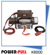
A new 2000 year model Warn XD9000i equipped with a 4.6 hp motor was shipped directly to ATS from a Warn dealer. See Figure 1 and Figure 2. The winch was unpackaged and subjected to a series of tests under a variety of load conditions. Each test was performed using the following general methods unless otherwise noted:
The wire ropes on the winch for these tests were new 5/16 in. diameter 7x19 galvanized wire ropes procured from Warn.
The wire ropes were marked with orange spray paint at 5 ft. intervals along their length so that their speed could easily be measured.
At the start of each test, the wire rope was spooled off of the winch drum until only half of the bottom layer remained on the drum. See Figure 3.
Testing Performed on Mechanical Brake
For the first set of tests, ATS mounted the winch into a mechanical brake apparatus provided by Mile Marker. The free end of the wire rope was wrapped onto the brake drum of the mechanical brake so that loading could be applied to the winch. The load on the winch was controlled by adjusting the pressure on the brake drum of the mechanical brake. See Figure 4.
For the purposes of these tests, ATS modified and instrumented the mechanical brake as follows:
The output signals for all instruments were connected to a data acquisition unit.
Electrical power for the winch was supplied by two 12-volt car batteries in parallel. These batteries were supplemented during testing with a 200 amp battery charger during actual winching. A 0-1000 amp. ammeter was used to measure the winch’s current draw.
The brake drum of the mechanical brake was shackled to the base of a 10,000 lb. load cell.
One J-type thermocouple was attached to the outside of the motor case. A second J-type thermocouple was mounted near the data acquisition unit to measure the ambient temperature.
The test brake was instrumented with a 0-2000 psi pressure transducer to monitor the pressure on the brake drum so that the applied load could be manually controlled.


